Geometry2D
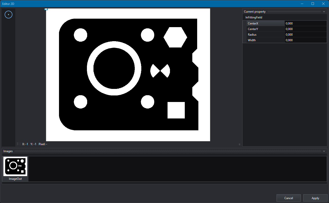
Editor2D is the tool used to create and modify some properties of OEVIS® objects in an easy and intuitive way, avoiding having to enter the values manually.
The window is divided into:
- Shapes panel: on the left side of the window, where all the linkable object are listed. To display also the sub-properties object it's necessary to check the Search inside internal properties checkbox when available.
- Visualizer: in the center of the window, where the image and the object are displayed and from which you can choose the necessary object or place it. The items available to be chosen will appear in orange and they will turn red once they have been selected. Under the visualizer there are the X and Y axes angle offsets, and the grayscale value of the point indicated by the mouse pointer.
- Current Shape panel: on the right side of the window, that contains the input properties of the created tool (so its name, the referring Geometry2D and the objects needed to the creation of the tool).
- Images panel: on the bottom of the window, in which there is the list of the available images that can be displayed on the Visualizer. The image selected doesn't affect the position of the object, it's only used as visual reference for a better understanding of what is happening.
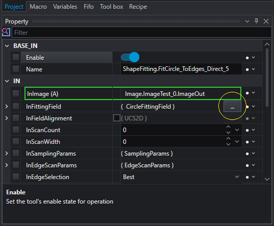
For example, if you take the ShapeFitting.FitCircle_ToEdges_Direct tool and click on the three-dot button to the right of the InFittingField property, the Geometry2D Editor will open.
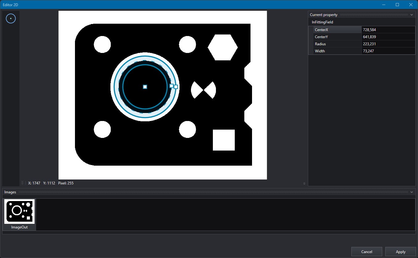
Press the button with the circumference in the upper left and draw the profile of the circumference you want to search for. You can use the various anchors of the tool to move, widen or narrow the inner, central and outer circumferences, to limit the search area. Press apply, this is just what is required to pass the correct parameters to the object FitCircle to identify the circumference.
Another use of the Geometry2D Editor is to easily draw labels for Metrology/Dimension objects to visualize the result.
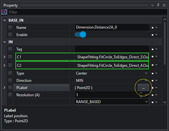
For example with the Dimension.Distance2A object select the PLabel property and click on the three-dot button to the right, to open the tool.
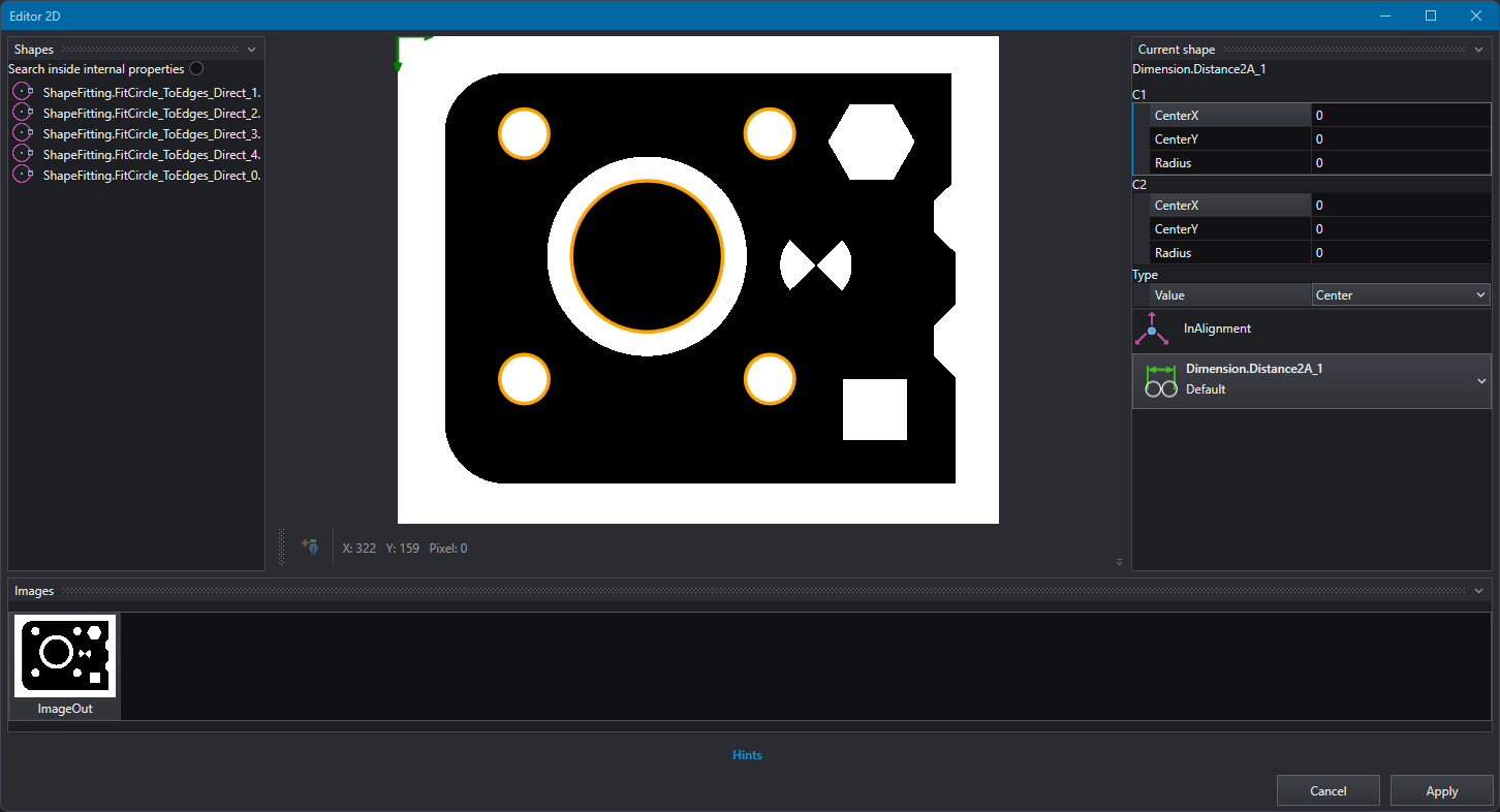
The list of available Shapes will appear; if not select the Draw creation pen if you want to modify the current label instead.
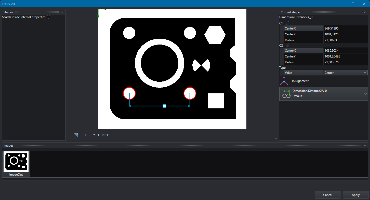
This tool requires two objects to obtain the distance, select them from the Shapes and then go into the image to drag the dimension line to the desired position. Alternatively you can choose the two objects directly from the draw and still drag the dimension line.