Camera Calibration Transform Editor
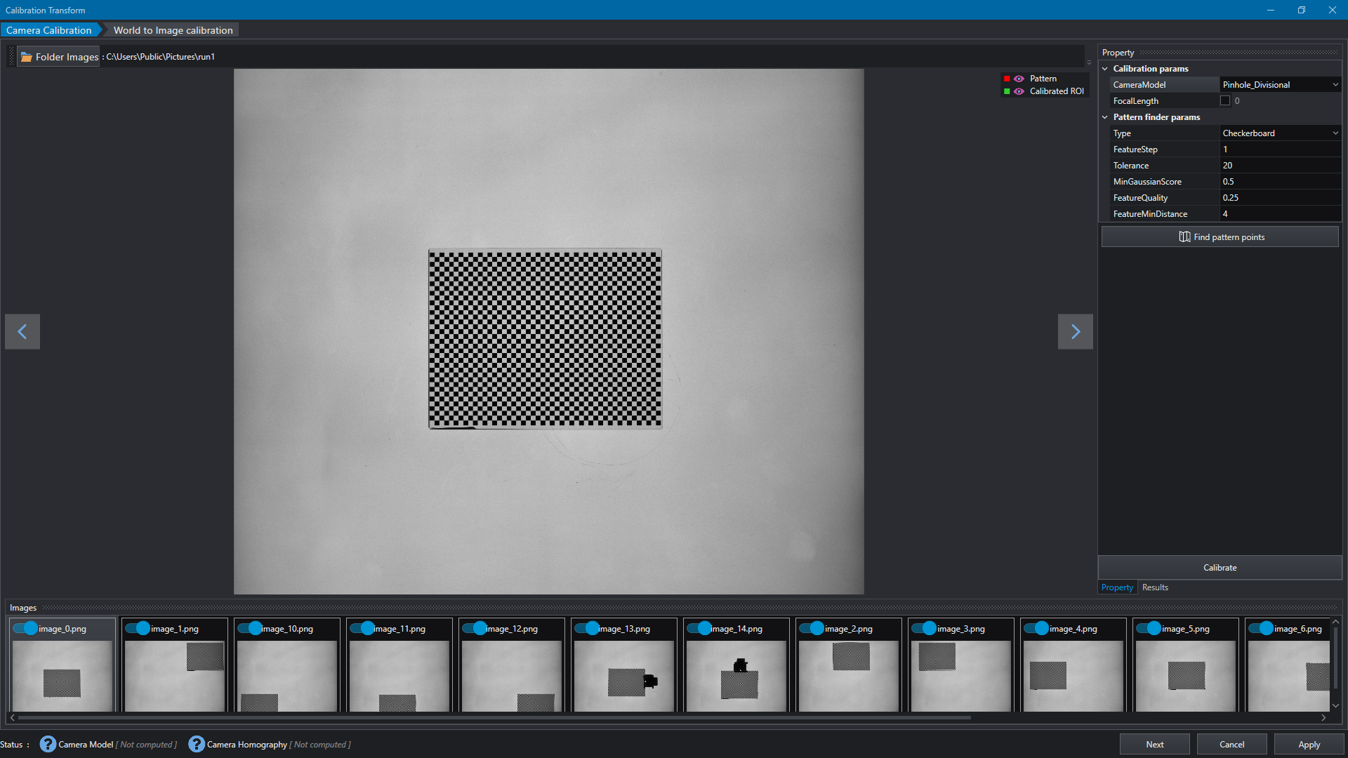
The Camera Calibration Transform editor is designed to assist in the creation of Camera Calibration Model to reduce image distortion and Camera Homography transform to map point from image coordinates to world coordinates. The Calibration Transform can be useful in application such as robot guidance.
The editor can be opened by any input property of type CalibrationTransform from any Tools implementing such a property type.
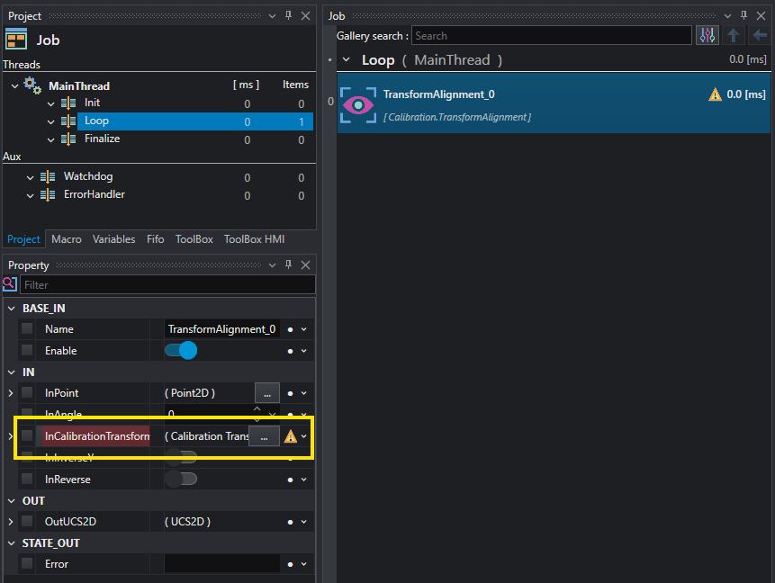
The calibration process is composed of two steps, the Camera Calibration and the World to Image Calibration. Each step can be performed independently and partial calibration can be applied. Anyway, to achieve the best result is recommended that both two steps are correctly executed.
Camera Calibration
The Camera Calibration is the first step of Calibration Transform and allows to estimate the Camera distortion model to compensate image distortion. To start calibration, select a folder of images using button Folder Images: the images must contain multiple views of calibration pattern, including tilted view when working with Pinhole models.
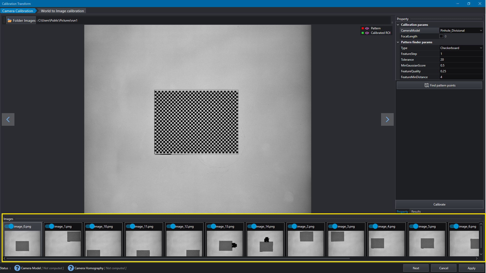
The list of images is displayed at window's bottom side and it is possible to switch between images and enable or disable the desired ones.
The property window allows to set up the camera model:
- Pinhole_Divisional: Pinhole camera model with divisional lens distortion model
- Pinhole_Polynomial: Pinhole camera model with polynomial lens distortion model
- Pinhole_PolynomialWithThinPrism: Pinhole camera model with polynomial with thin prism lens distortion model
- Telecentric: Telecentric camera model, based of the TCLib suite calibration algorithm
- Radial: Radial only distortion camera model
Based on the selected model type, other properties can be set for the calibration model, such as the focal length for Pinhole models, the crop mode for Telecentric and distortion center for Radial.
For a detailed description of Camera Calibration parameters see CalibrationParams.
Pattern finder parameters can be adjusted as well in order to fit different type of patterns; three types of pattern can be used in the calibration process:
- Checkerboard : pattern based on chess features
- CircleGrid : pattern based on circles features
- ChArUco: pattern based on ChArUco board
For a detailed description of Pattern finder parameters see PatternFinderParams.
By pressing the Find pattern points button it is possible to extract pattern features for each enabled images. Points are displayed in overlay with the currently selected image. To start calibration process, press the Calibrate button.
Note
The Find pattern points is an utility step which allows to inspect each images before the calibration is performed; the pattern points are extracted in any case when Calibrate is pressed.
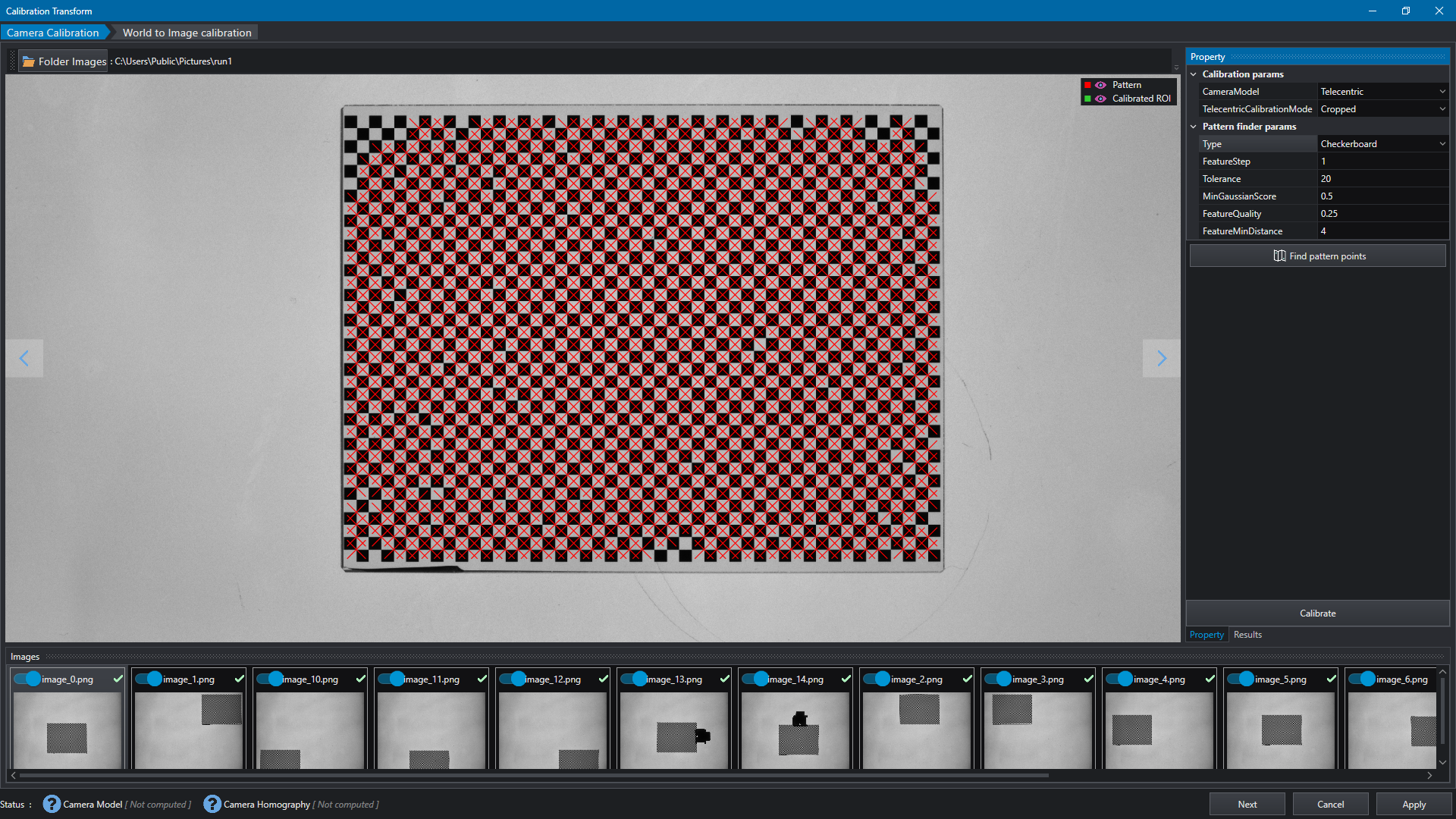
Once the calibration process is completed, the calibrated region is displayed over the image and summary is prompted in Results window; it is possible to hide the geometries on the viewer using the hide/show buttons at the top-right corner.
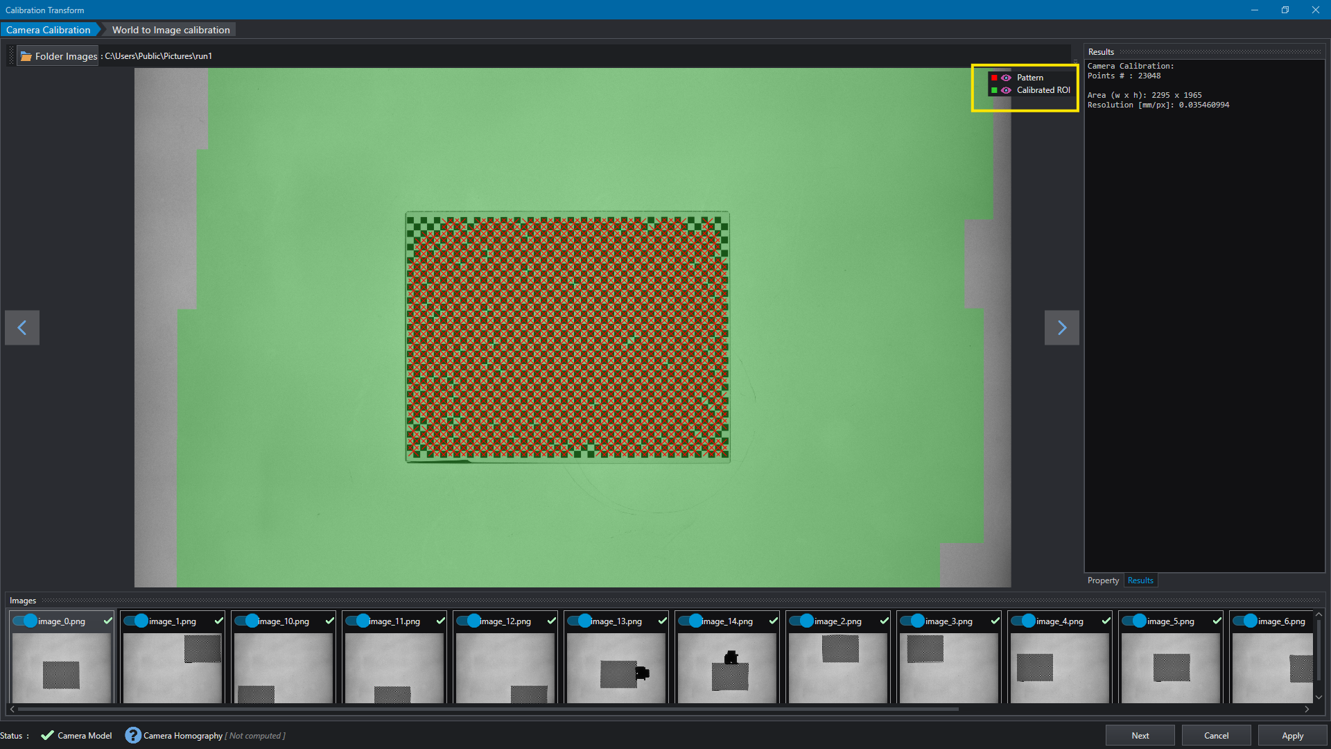
To proceed with next step, press the World to Image transform tab at the top of the page or the Next button at the bottom or accept to continue in the message displayed after the calibration procedure.
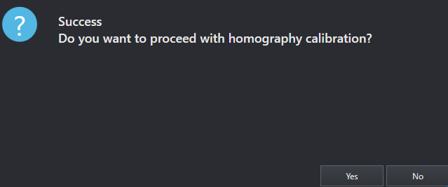
World Image Calibration
The World to Image Calibration is used to estimate the homography to transform points and shapes from Image to world coordinates and viceversa. The process is similar to Camera Calibration: a list of images with pattern views are required; this time only flat pattern views are required.
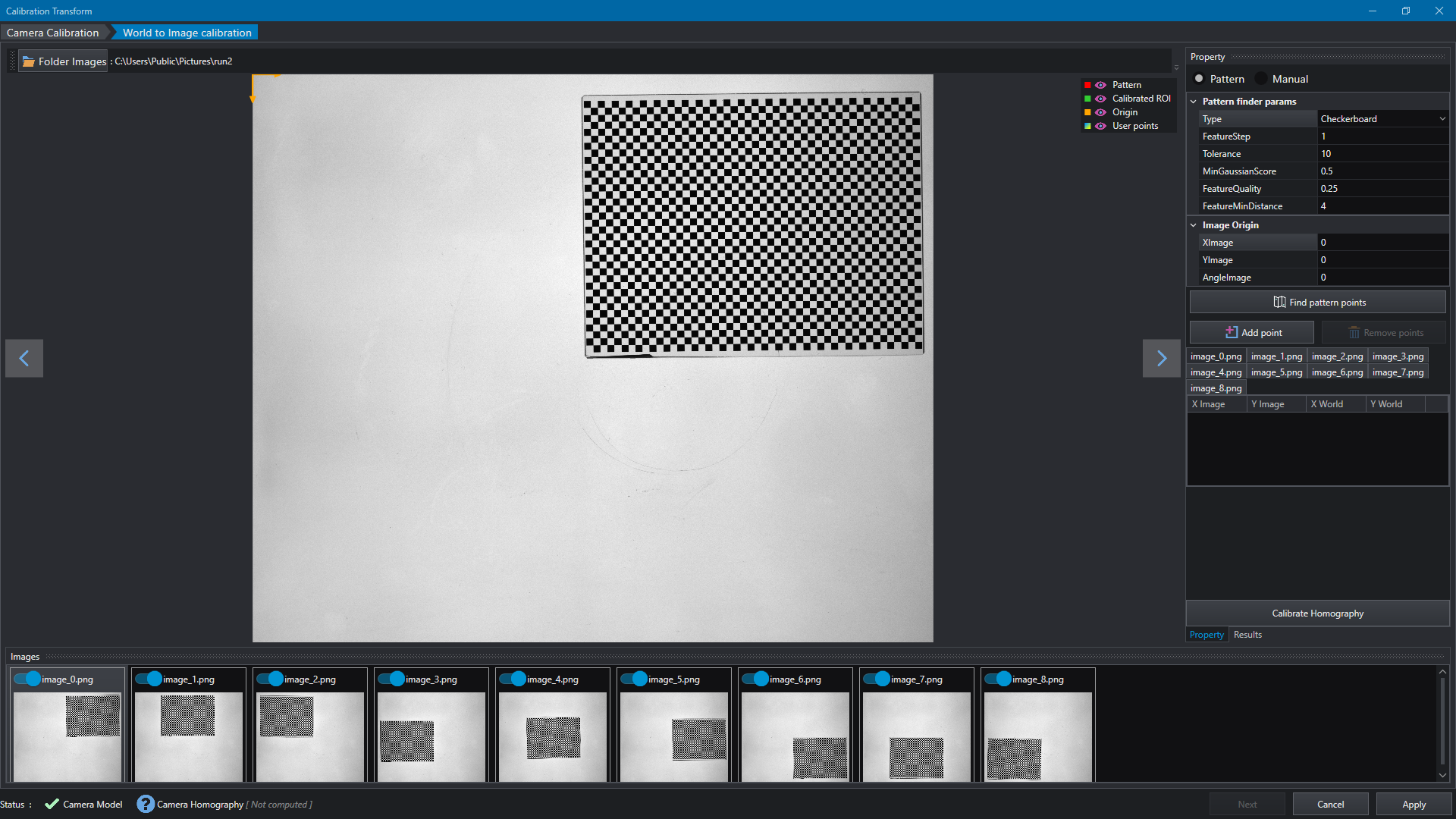
The calibration requires to insert at least four points in the Image world and their correspondent coordinates in the world coordinate system. To accomplish this task, two methods are available : the pattern based method and manual method.
Pattern method
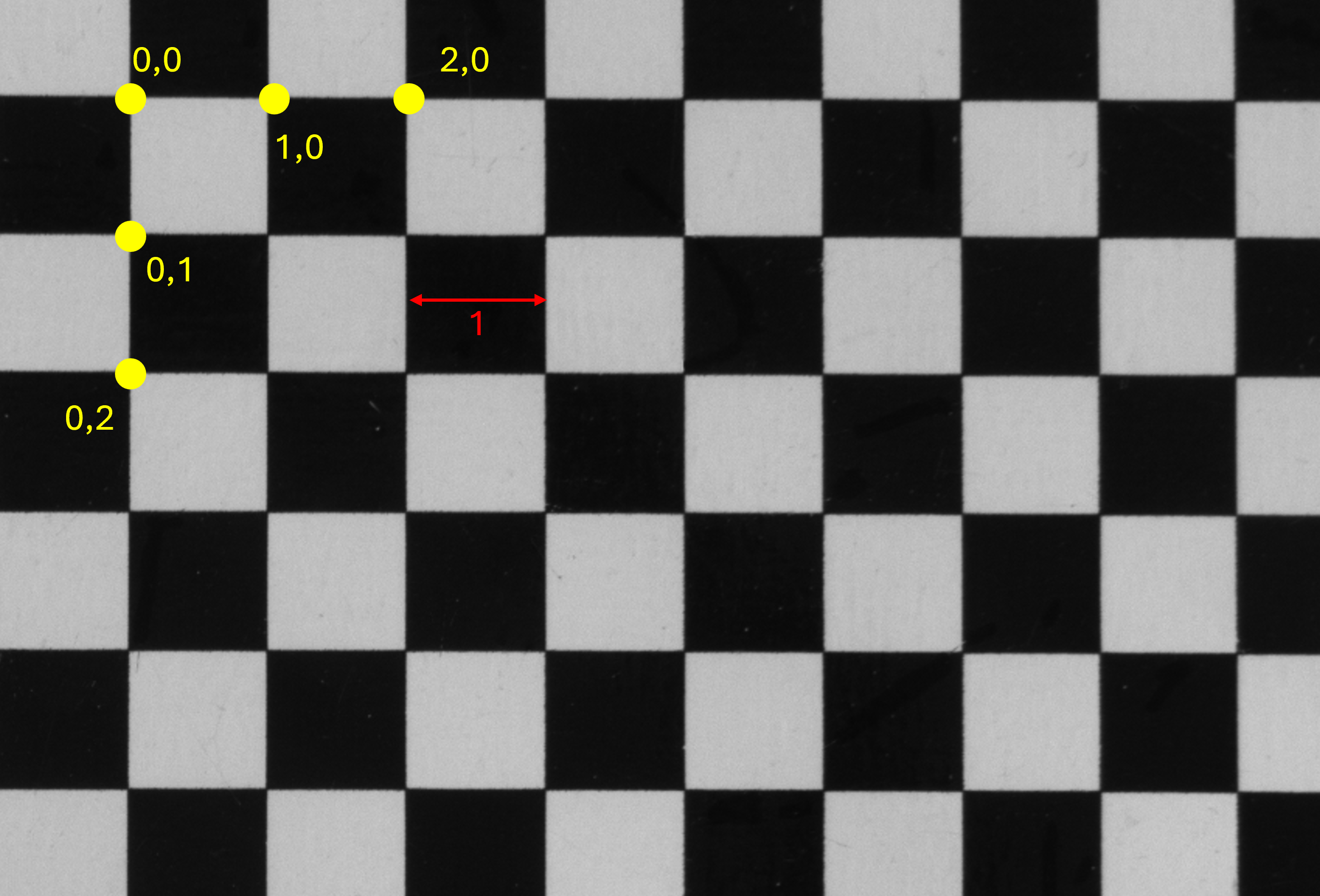
By selecting the Pattern method, images of multiple views of pattern can be used to extract pattern points and match them with world coordinates; in this case, the top-left point of the extracted points is marked as (0,0), then the others points will follow the pattern grid based on FeatureStep value. For example, if FeatureStep is set to 1mm the world coordinates of the extracted points will follow the pattern (0,0), (1,0), (2,0)... etc. It is important to notice that during the points extraction process each image is processed independently, so the top-left point of each image will be marked as (0,0), then each image is adjusted to the first image in the list to compute the final homography.
To extract the pattern points press the Find pattern points button; the list of coordinates for each image is computed.
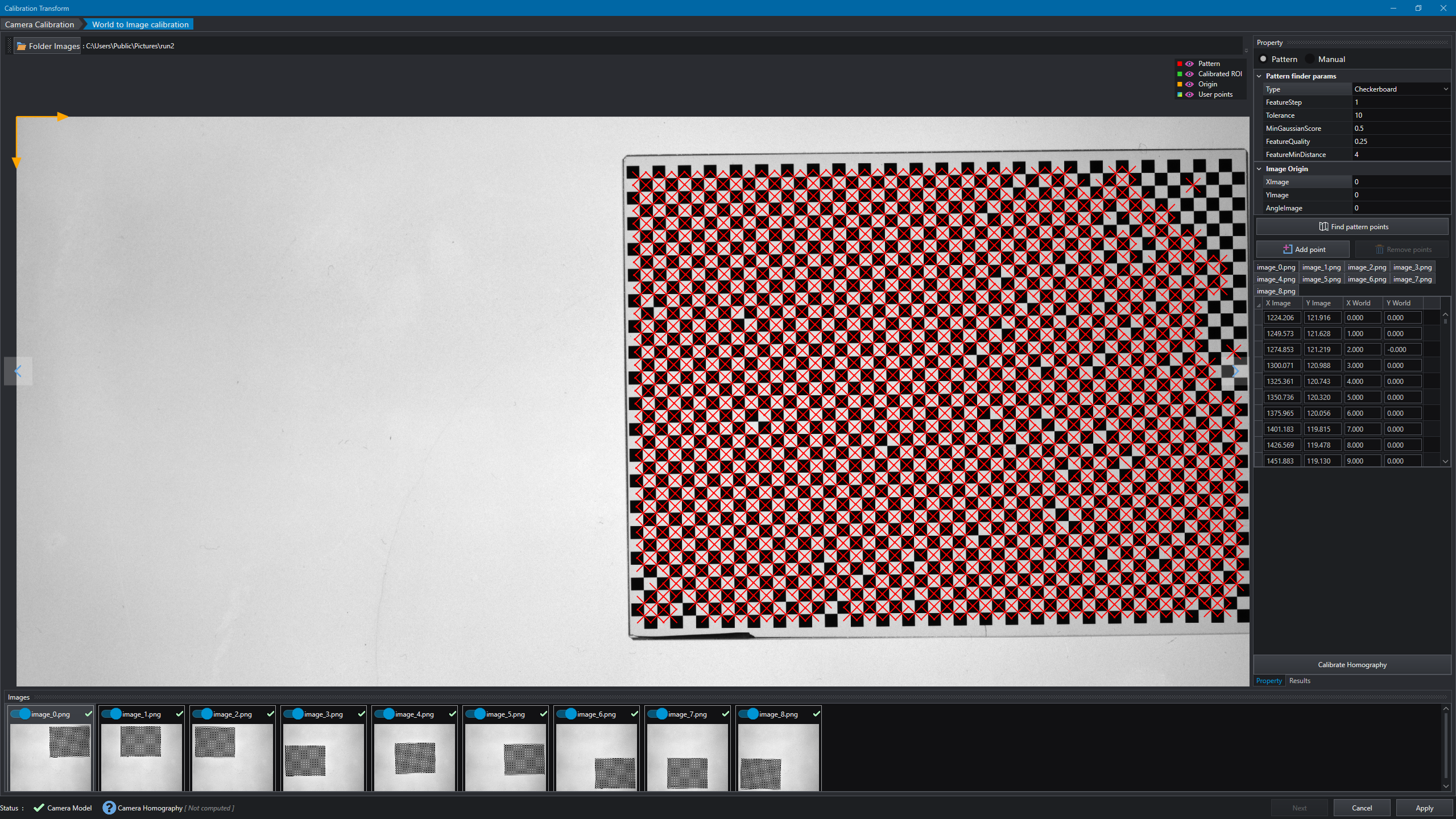
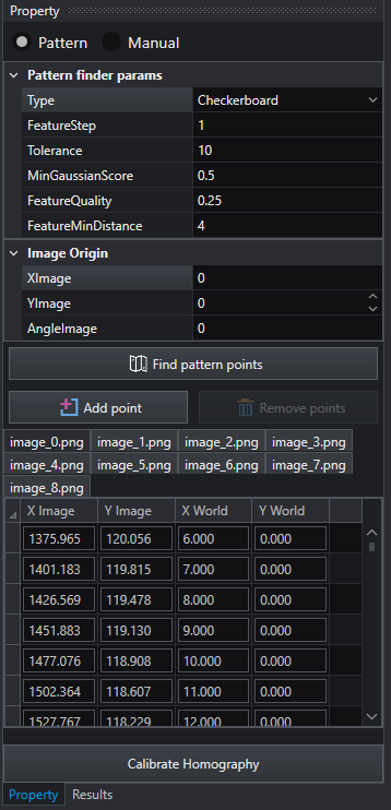
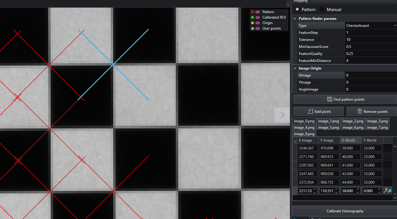
It possible to adjust points for each view by adding missing points or remove undesired points.
Note
When adding manual points in pattern mode it's important to remember that the world coordinates of newly added points must follow the grid coordinates starting from top-left point.
Manual method
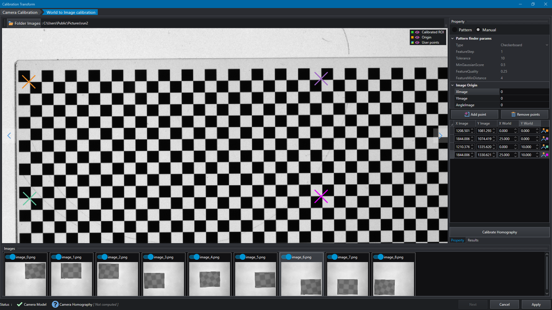
Manual method allows to insert points by clicking on the selected image and edit their world coordinates; in this case only one list of points is used. Press the Add point button and click on the image to insert new point in the desired position, the new point is displayed in the list.Every user point has a different color in order to be easily recognized in the view.
Homography
To start the homography calibration press the Calibrate button; the calibration will take the extracted point based on the chosen method. When procedure is completed the calibrated region, i.e. the region covered by the points used in the estimation procedure, is displayed and a summary with of computed results is displayed in the Result window.
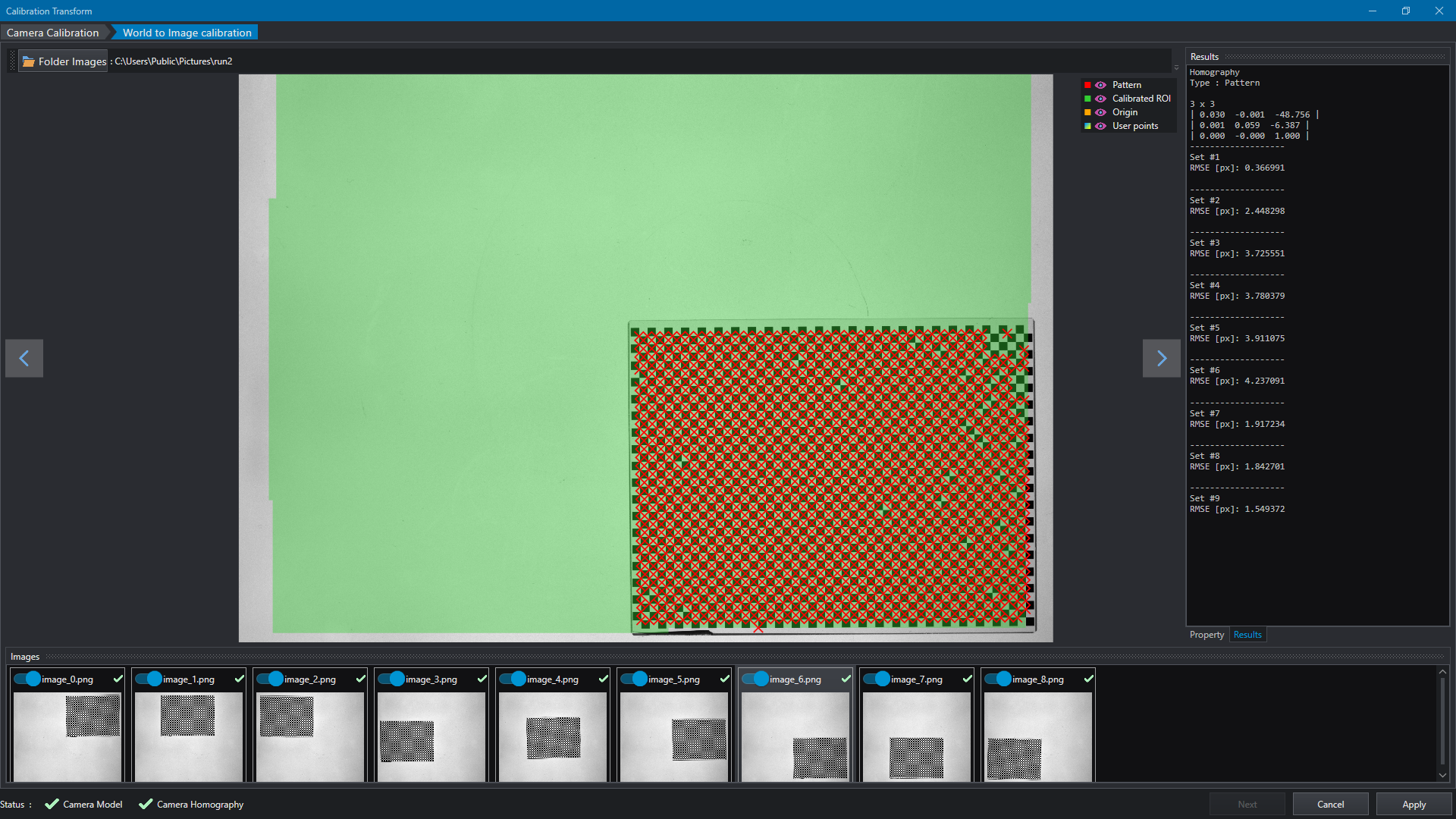
Depending on the steps have been performed, calibration status is displayed at the bottom-left of the page.

The computed Calibration can be applied to the source property that opened the editor. When saving the project, the calibration model is saved into a separated file alongside the project file with extension .ctmdl.