Calibration Transform
CameraCalibration
This example shows how to perform camera calibration and homography estimation using standard tools.
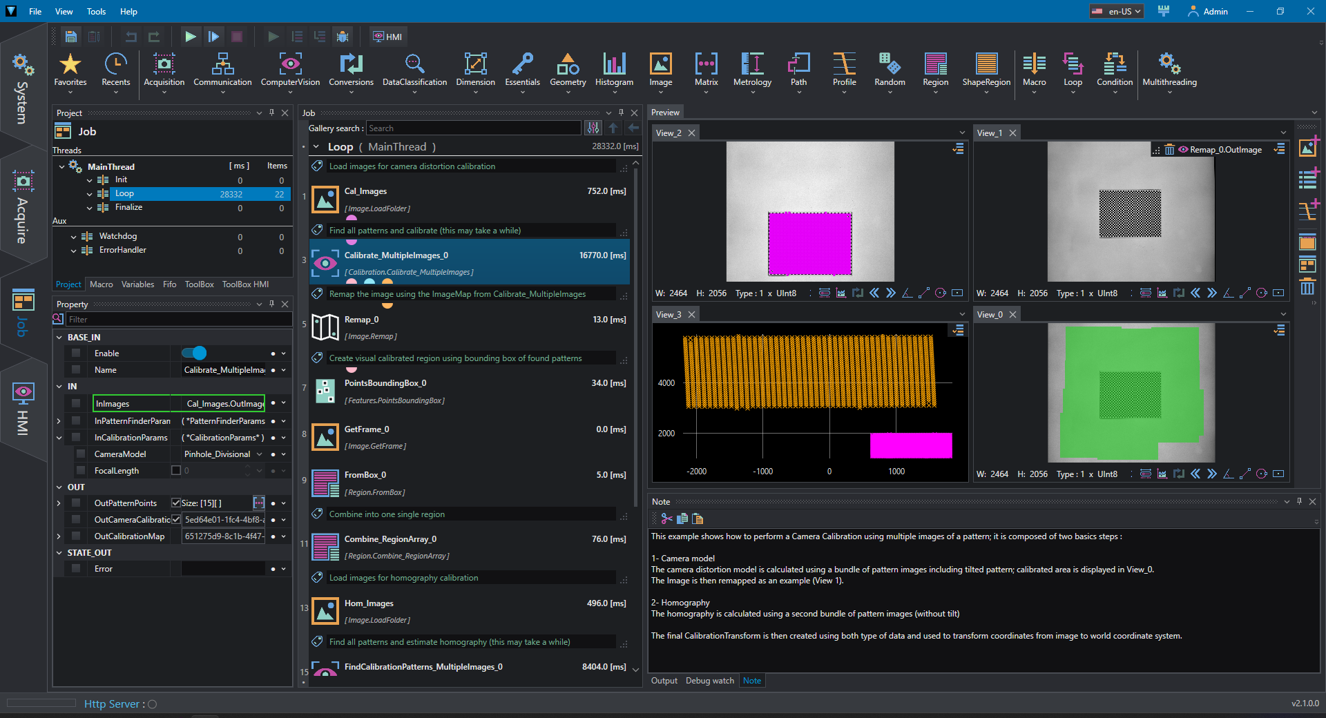
The first step is the camera calibration: the folder with multiple pattern images is loaded in the project, then the tool Calibrate_MultipleImages is used to calibrate the camera based pattern and camera parameters (in this case a checkerboard pattern is used and a pinhole model is considered). The calibration outputs are
- CalibrationMap: can be used to remap the undistorted image
- CameraCalibration: used in CalibrationTransform to consider lens distortion when remapping points and shapes,
The calibrated region is computed as well as the sum of bounding box of the found pattern points.
The second step is the homography estimation: the homography allows to transform coordinates from the image reference to the world reference and viceversa.
The images pattern are load from a second folder and their points are extracted: the points in each pattern image are computed as AnnotatedPoint, a pair of pixel coordinates and world coordinates, where the world coordinate is calculated based on pattern FeatureStep and the top left point of the pattern is the (0,0); this means that in world reference each point has coordinates (i x FeatureStep, j x FeatureStep), where i,j are the indices of the point in the pattern grid.
The homography is computed by EstimateHomography_FromAnnotatedPointsArray.
Once the two calibration phases are performed it is possible to create the CalibrationTransform using CreateCalibrationTransform_CreateFromObject given both the CameraModel and homography Matrix.
Note
The CalibrationTransform can be created using both CameraModel and Matrix or just one of them, depending on the accuracy and application's requirements.
CameraCalibration_HMI
This example shows the camera calibration and homography estimation procedure with an interactive HMI. This application is a simplified version of Calibration Transfrom Editor and it is used to demonstrate HMI capabilities creating a Calibration project that can be modified and used by users.
It is composed by three tabs:
1- Camera Model: Parform camera calibration using pattern images.
2- Homography [ Pattern ]: Perform homography estimation using pattern images.
3- Homography [ Manual ]: Perform homography estimation using provided custom points.
The selected tab index is connected to the Switch condition in the main loop and which activates different routines.
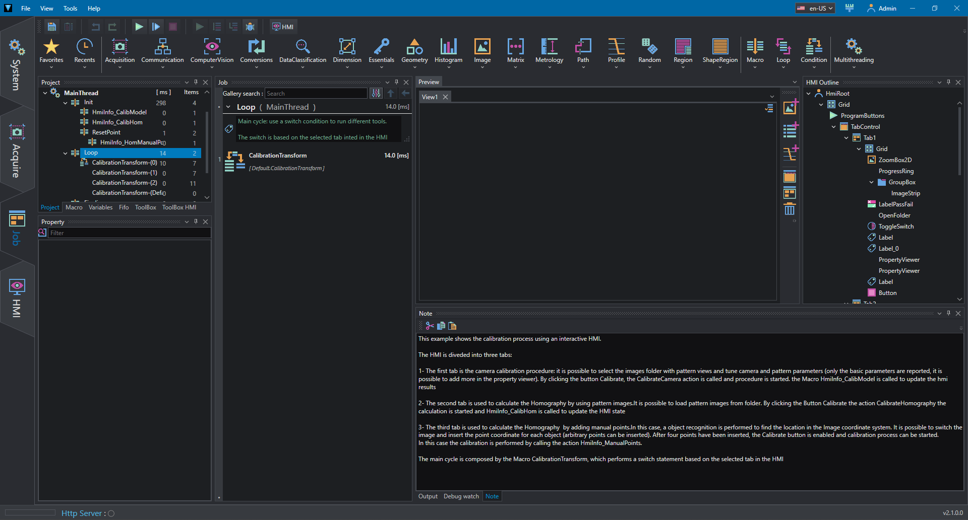
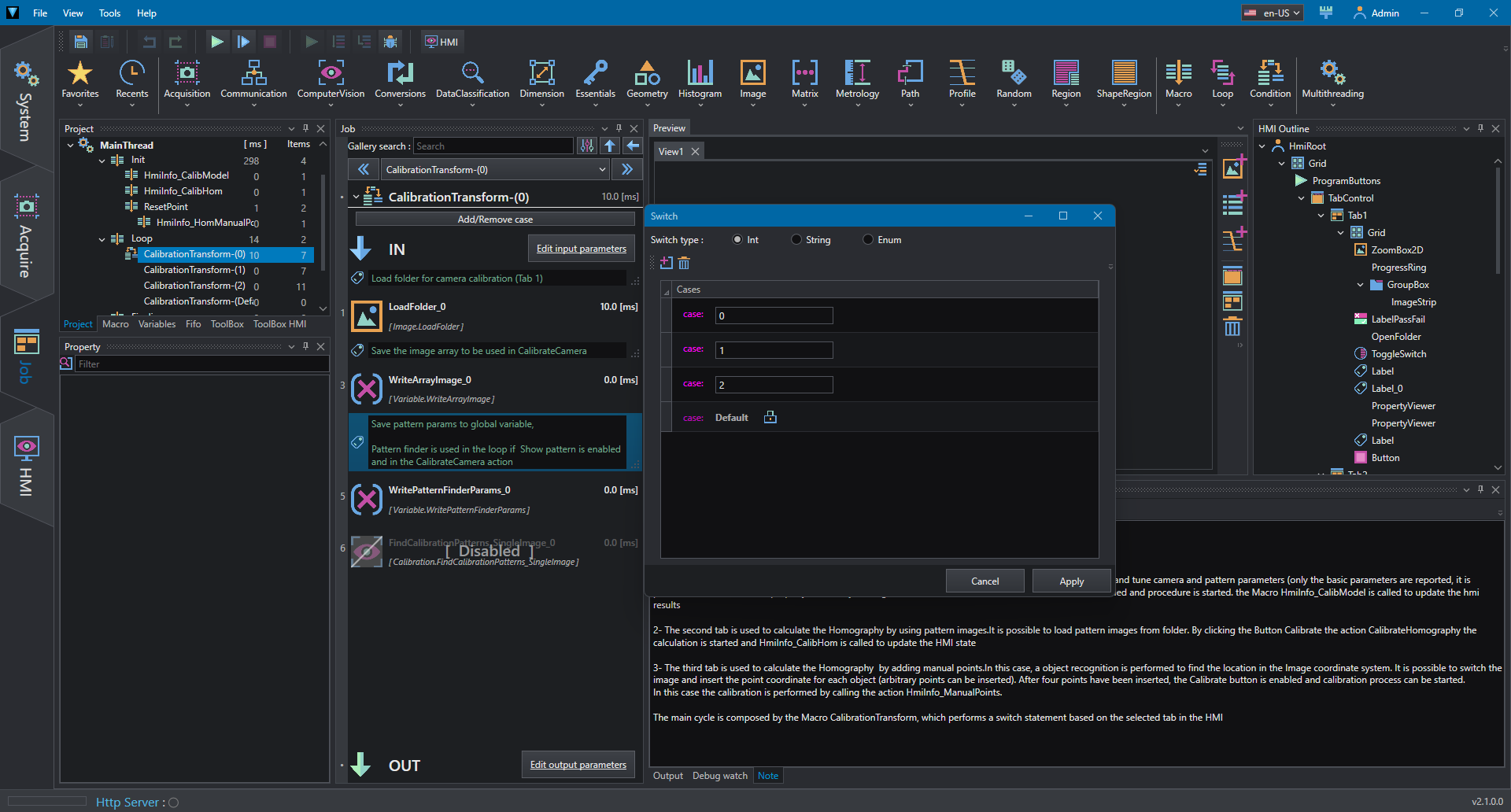
Macros and Actions are used to refresh HMI state and create interactions:
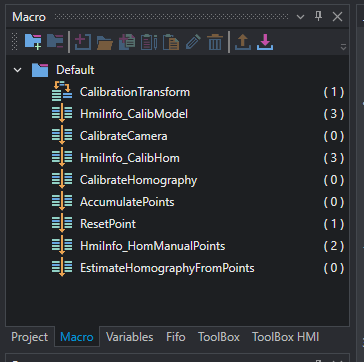
- HmiInfo_CalibModel: used to update Hmi when Camera Model tab is selected.
- CalibrateCamera: calibrates camera model (invoked from Button).
- HmiInfo_CalibHom: used to update Hmi whem Homography [ Pattern ] tab is selected.
- CalibrateHomography: estimates homography from pattern (invoked from Button).
- AccumulatePoints: add manual points to array in Homography [ Manual ] tab (invoked from Button).
- ResetPoints: resets manual points.
- HmiInfo_HomManualPoints: used to update Hmi whem Homography [ Manual ] tab is selected.
- EstimatedHomographyFromPoints: estimates homography using manual points (invoked from Button).
CameraCalibration_HMI - Camera Model
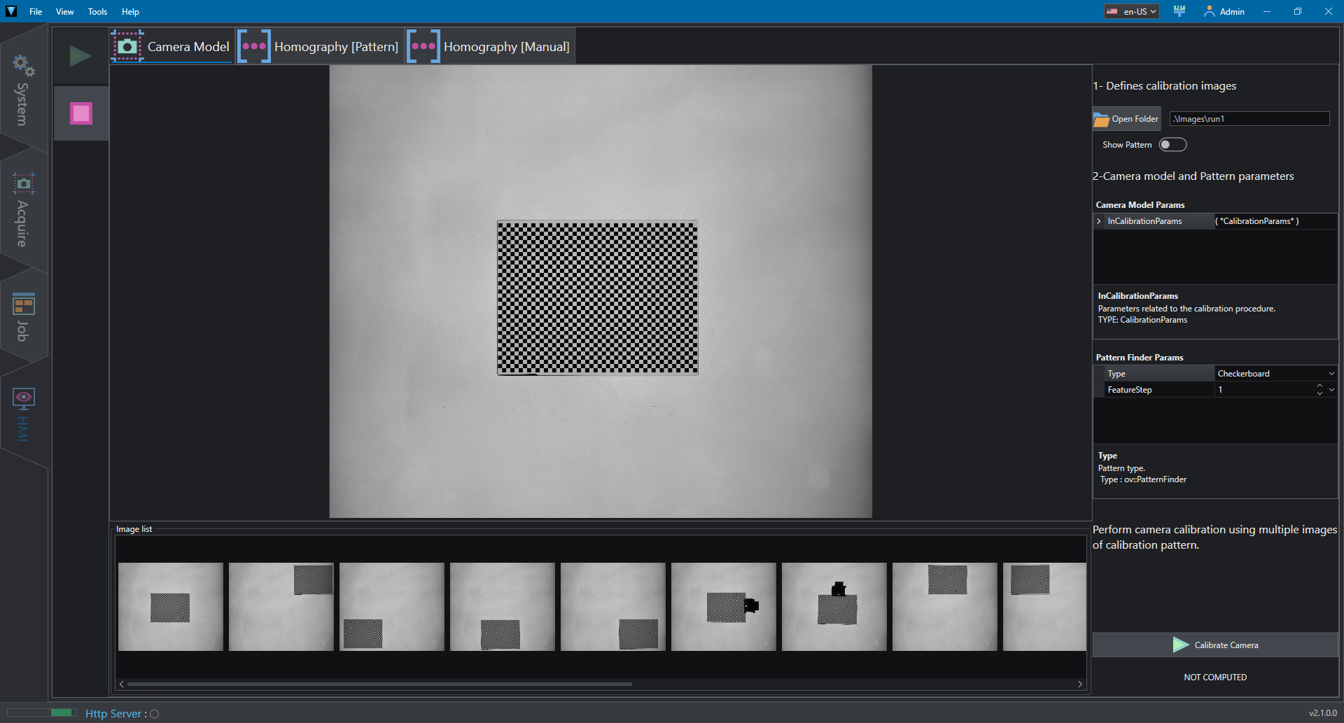
The Camera Model tab allows to calibrate camera distortion using pattern images and activates the Switch case 0.It is possible to select the desired folder using the Open Folder button. The ImageStrip control shows the list of loaded image in the loop and allows to select the main image to visualize; on the selected image it is possible to activate the pattern preview with Show Pattern.
Camera model and pattern parameters can be adjusted in the PropertyViewer controls with the commonly used properties.
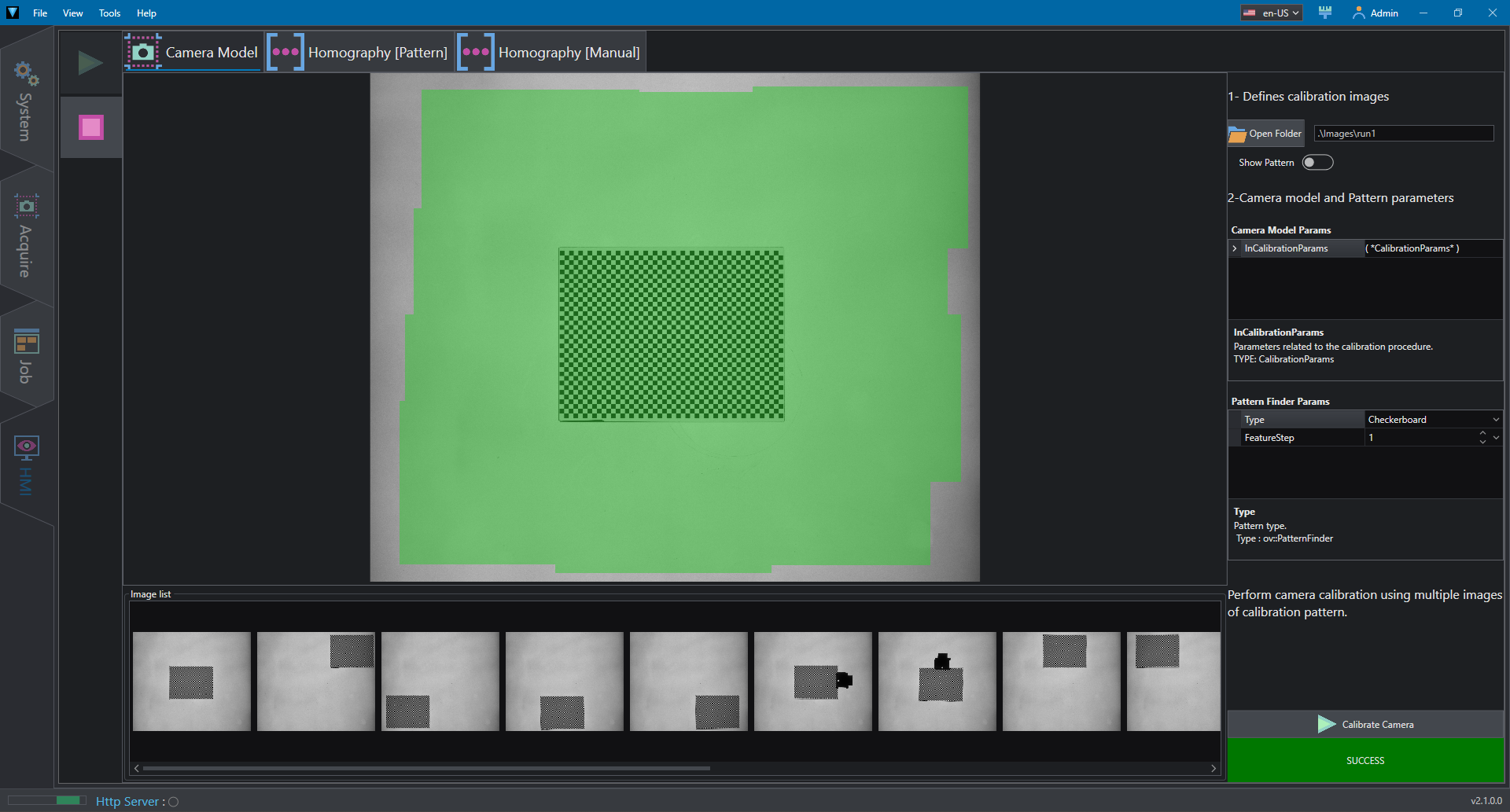
The calibration process, triggered by Calibrate Camera button, is performed by CalibrateCamera action and calibrated region is displayed.
CameraCalibration_HMI - Homography [ Pattern ]
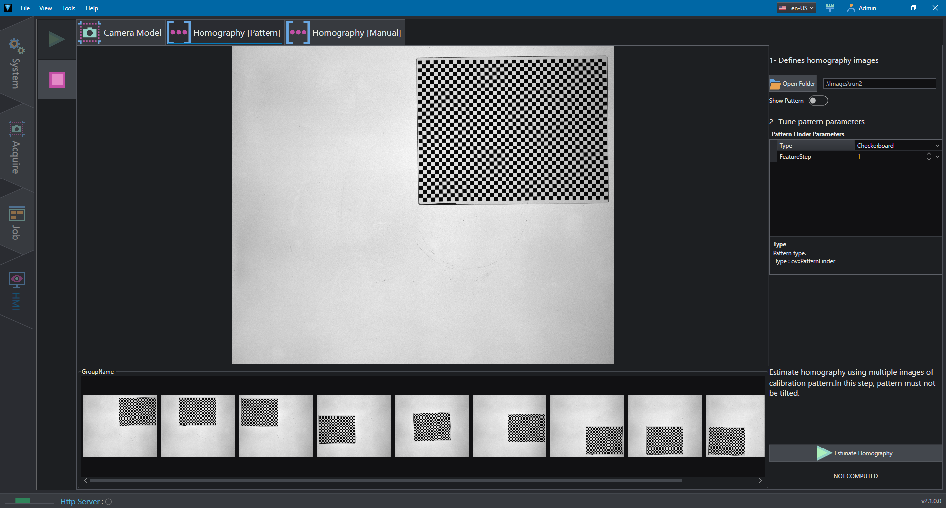
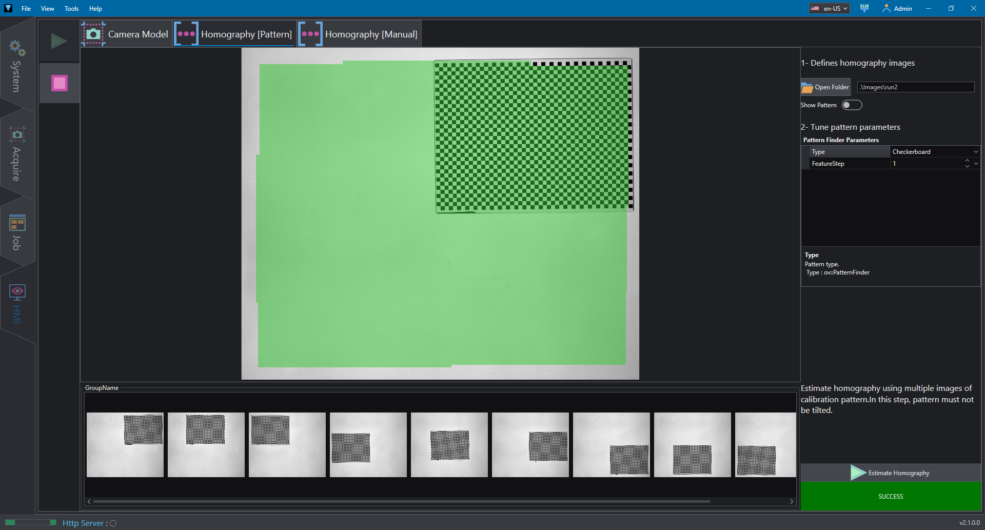
The Homography [ Pattern ] tab allows to estimates homography from pattern images and activates the Switch case 1.It is possible to select the desired folder using the Open Folder button. The ImageStrip control shows the list of loaded image in the loop and allows to select the main image to visualize; on the selected image it is possible to activate the pattern preview with Show Pattern.
Pattern parameters can be adjusted in the PropertyViewer controls with the commonly used properties.
The estimation process, triggered by Calibrate Homography button, is performed by CalibrateHomography action and calibrated region is displayed.
CameraCalibration_HMI - Homography [ Manual ]
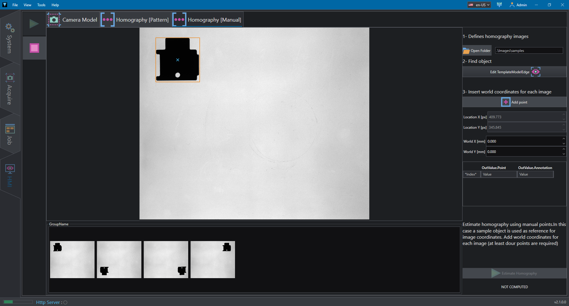
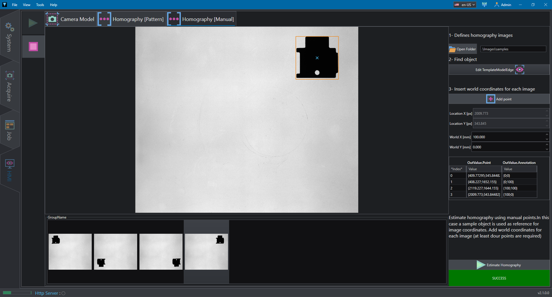
The Homography [ Manual ] tab allows to estimates homography with manual points and activates the Switch case 2.It is possible to select the desired folder using the Open Folder button. The ImageStrip control shows the list of loaded image in the loop and allows to select the main image to visualize. To estimate the homography with custom points we have to insert the pixel and world coordinates for at least four points. To simplify this process in the example a Template model is used to locate the center of a reference object in four images that will be used for pixel coordinates.
The template model can be inspected by opening the editor.
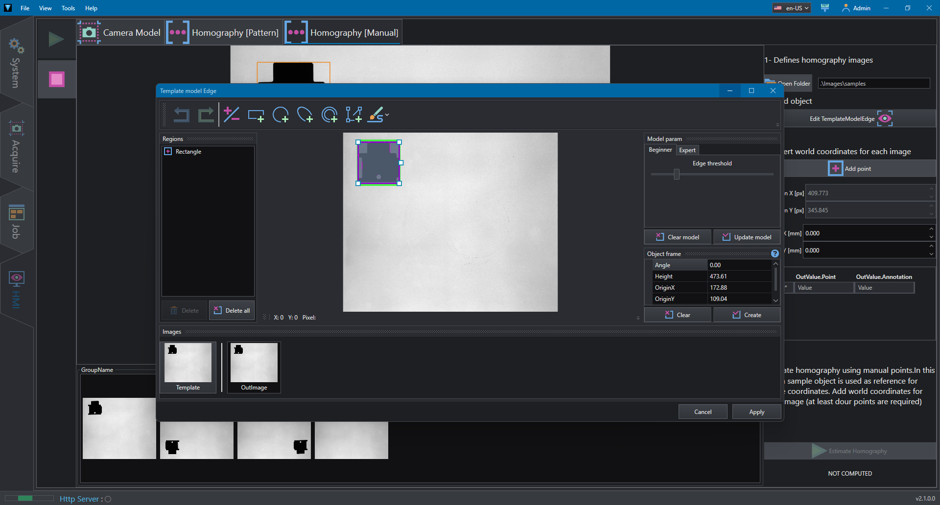
Pattern parameters can be adjusted in the PropertyViewer controls with the commonly used properties.
The estimation process, triggered by Calibrate Homography button, is performed by CalibrateHomography action and calibrated region is displayed.
By changing the selected image it is possible to insert the points coordinate and fill the table.
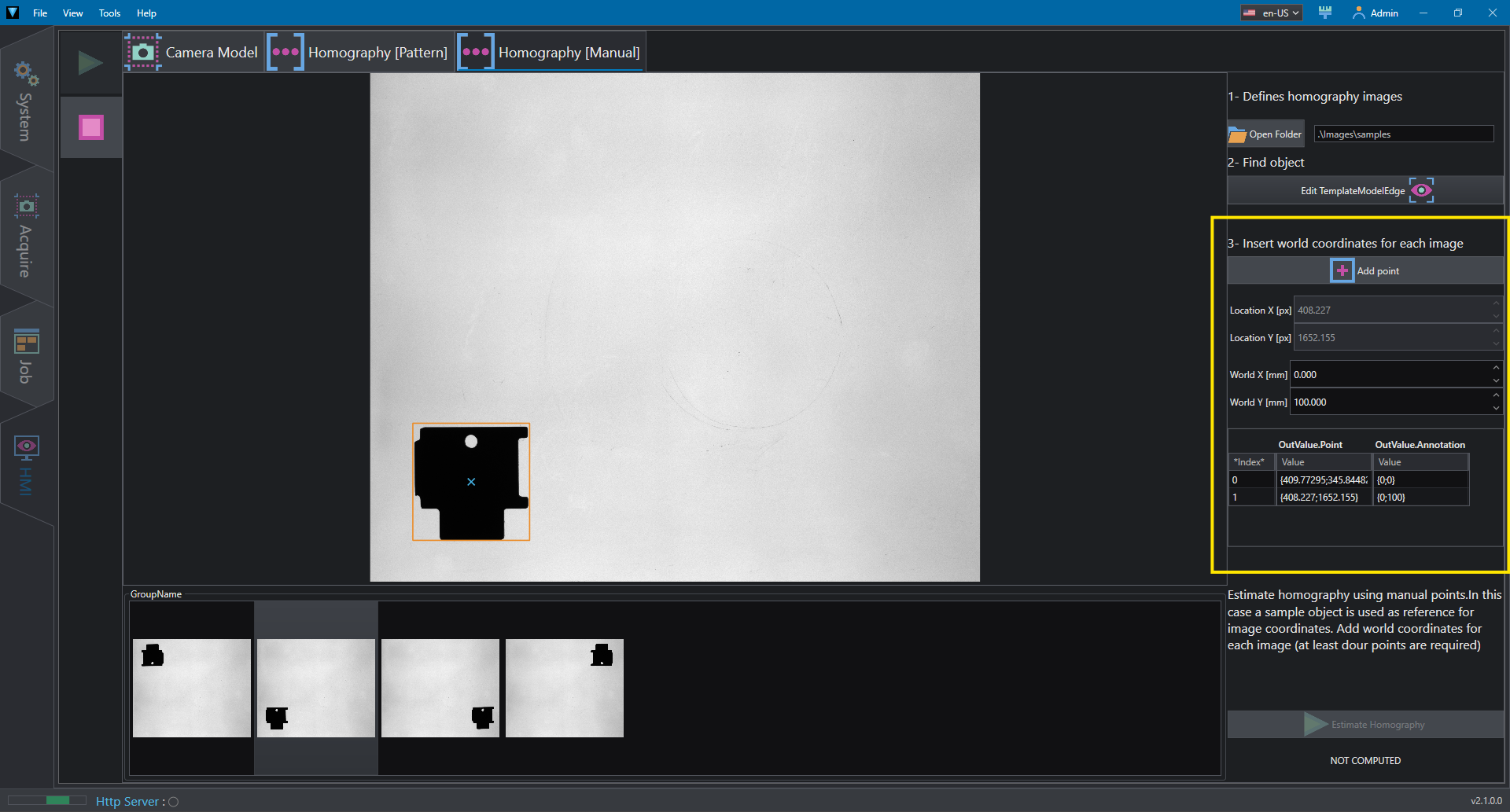
To simplify the process we can insert the points: - (0,0) - (0,100) - (100,100) - (100,0)
Once the number of four points has been reached, the Estimate Homography is enabled.