Programming Reference
In this section you will find details on how to program simple and complex logic in OEVIS®.
Programming in OEVIS® is based on the principle of data flow. The conventional flow of data in OEVIS® has a top-down direction, like in usual flow charts. Data is characterized by its type and its value. The type defines the meaning of the data: for example, the type Circle2D represents a circle in a 2D plane, containing values for the X and Y coordinates of its center and for the length of its radius.
Data can be of simple types, structured types or iconic types. Examples:
Floatis a simple type representing a floating point number;Stringis another simple type representing a sequence of characters;Point2Dis a structured type, composed of two fields: X and Y coordinates of the point, which are both ofFloattype;Regionis an iconic type which has no explicit fields.
Programmer insight
Structured types are exactly like struct in C++ and C#. Iconic types are like struct with exclusively private members and fields.
Data can be in the form of single values or collection of values. Collection of values are called arrays.
Programmer insight
Arrays can be of generic type and are similar to std::vector<T> in C++, T[] in C# and lists in Python.
Data is meant to be processed by Tools. Tools are the programming building blocks that allow the user to build its own complex logic and data elaboration algorithms. Input and output parameters of the tools are called Properties. Data flows into the tools through the tool input properties, get processed and flows out through the tool output properties. The results of the execution of a tool will be available only after the project (or the tool) has been executed at least once.
Input properties can be manually set to a specific value or can be linked to previous tool results. Linking tools is the fundamental principle of building a program in OEVIS®.
Linking analogy
Imagine linking tools like connecting a water pipe to a water faucet in order to fill up a bucket. The water faucet can be viewed as the output of one tool, the water flow is the data passing between tools and the bucket represents the input of the subsequent tool.
Furthermore, to store data temporarily or during subsequent loops of the project execution, it is possible to use variables. Variables can be of any supported data type, including arrays. Variables can be read from and written into with discrete operations, allowing the implementation complex data retaining logic.
Linking
Links between tools represent the channel that transports data between different points of the program. Links are created always from the destination input property and are built referencing any output property of any tool placed before the destination one.
Data consistency
If the data flows top to bottom during the execution of the program, it is trivial to say that creating a link that goes in the opposite direction of the program logic has no practical sense. The destination would have already been executed and the link would loose any meaning.
If you want to create persistence between subsequent iterations, you have to use variables.
A link can be created in two ways:
- Automatically: some complex typed properties (e.g. Image, Region) are automatically linked to the last available data output. Auto-linking properties are identified the "(A)" tag next to their name.
- Manually: using the property linker after the tool has been created.
The property linker, if available, is accessed by clicking on the rightmost dropdown available in every property field.
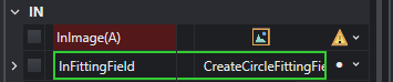
As seen in the previous image, if the property is mandatory, the dropdown menu presents a warning icon, otherwise a white bullet point. Clicking on the dropdown shows a contextual menu that collects all the supported and available data outputs for the chosen property. In the following example shows that only the outputs of previous tools are available in the property linker menu.
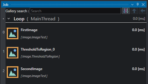
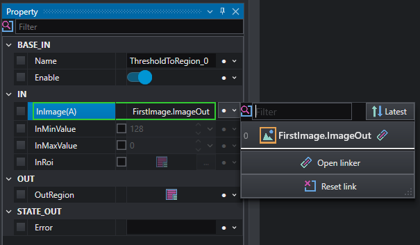
Once the property has a value linked with it, a green rectangle will surround it.
It is possible to filter the available link sources by name using the Filter field. It is also possible to order the link sources in ascending or descending order with respect to the data flow.
By clicking on the Reset link button the link is deleted.
When a tool is selected on the job tool list, its links are represented by circles split between source and destination property with the following color convention:
- Image
- Region
- Path
- TemplateModel
- ImageMap, CalibrationMap
- All Geometry2D types
- Structures
- Other types (numeric, strings, ...)
Link conversion
In order to facilitate the connection between tools, some conversion and data adaptation is automatically executed by the linking engine.
Conversions can be lossy or lossless. For example, converting a floating point number (Float data type) to an integer number (Int data type) is lossy, because 4.532 gets truncated to 4 when converted. Conversely, from Int to Float there is no data loss.
If a link with automatic conversion is created, the property will be highlighted by a yellow border.
Programmer insight
This behavior is analogous to a type cast. The conversion logic for numbers that is used in OEVIS® is cast only, so it truncates the value to the decimal point. If you need to round before casting, use the specific rounding tools.
float myVal = 3.5f;
int i = static_cast<int>(myVal);
float myVal = 3.5f;
int i = (int)myVal;
Link vectorization
Another automation that can be executed by the linker engine is called vectorization. This operation allows to connect an array of values to a tool which normally accepts a single data value, automatically causing the tool to iterate on all array elements. The output of the tool will increase in dimensionality accordingly. This automation can remove unnecessary complexity to parts of the program and makes the data flow easier to follow.
Example
The user links Array<Image> to a Image.ThresholdToRegion tool. The output becomes Array<Region> with the same size as the input array. It contains a collection of Region obtained by the thresholding operation executed on each Image of the original array.
Programmer insight
This behavior is analogous to the for-each control flow statement in procedural programming language
for (int i = 0; i < array.size(); ++i)
{
    ...
}
foreach (var item in collection)
{
    ...
}
It is possible to link multiple single data value input properties to multiple arrays. In this case the tool will execute element-wise on the multiple arrays.
Example
The user links Array<Image> and Array<Int> respectively to the InImage and InMaxValue properties of an Image.ThresholdToRegion tool. The output becomes Array<Region> with the same size as the two input arrays. It contains a collection of Region obtained by the thresholding operation conducted on each Image of Array<Image> with each threshold value of Array<Int>, taken with the same index.
Warning
This behavior only works if the two (or more) connected arrays have the same size. If the size is different the tool execution will rise an error.
Arrays
Arrays are an ordered collection of data. They can be empty or they can have one or more elements. In OEVIS® every data type T has its own corresponding 1D and 2D array Array<T> and Array<Array<T>>.
OEVIS® offers a variety of tools for operations on arrays.
The Array Editor can be used to manually edit array properties.
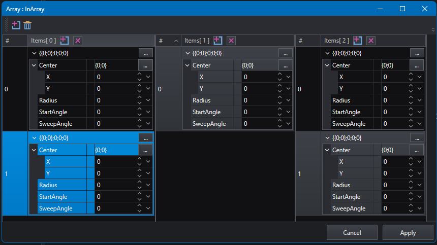
Array<Array<Arc2D>> collectionNullable and Conditional execution
Nullable types can store NULL value for a particular type of data.They are identified by ? symbol, for example Image? can be an image or NULL , Int? can be a 32-bit integer value or NULL and so on.
Nullable type are defined also for array type:
-
NullableArray<T>: contains a collection ofTdata orNULL(es.Image?Array,Int?Arrayetc.).{1 , 5 , NULL , NULL , ...} -
NullableArrayArray<T>: contains a collectionNullableArray<T>as in the previous definition; in this case each array can also beNULL{ {1 , 2 , 3 } , {4 , NULL , 5 , 6 } , NULL , ... }
Link to a nullable type can have an effect to job execution, see following example.
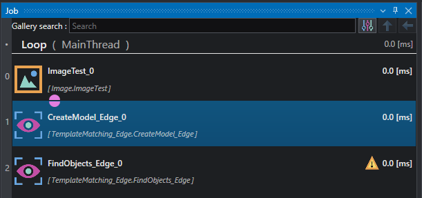
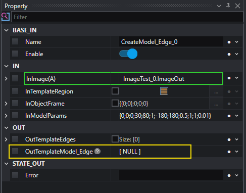
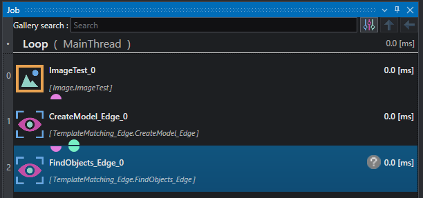
The tool CreateModel_Edge has nullable output OutTemplateModel_Edge , which means the result can be a valid model or NULL if the parametrization is not correct. If we link the output to FindObject_Edge the entire tool becomes Conditional; in this case the execution of the tool depends on the output of CreateModel_Edge : if the model has been correctly created FindObject_Edge can be executed, otherwise if the model is NULL the execution is skipped.
Variables
Variables are data containers, identified with a name. Each variable in OEVIS® must be of a specific type, declared at the moment of the variable creation. As all types can be made into arrays, also variables can be of array type.
Example
Some typical uses of variables are inspection results counters, configuration information holders, or constant reference values for the execution of the program.
Variables are managed within the variables editor.
Variables retain values between different iterations and have global project scope. The user can link an input property to a variable or can atomically read and/or write the variable with dedicated tools.
Info
Linking an input property directly references the data stored in the variable. Reading the variable with the dedicated Read tool creates a clone of the data stored in the variable. This can be useful when using variables across different threads because it avoids race conditions between threads.
Warning
Variables are globally scoped. This means that changing the value of a variable inside of a macro could impact other parts of the program.
Advanced programming
OEVIS® allows the user to program and define complex execution logic with the following advanced functionalities:
-
Macros, loops and conditional execution
-
Handle exception with Try/Catch and ErrorHandler
-
Write your own custom C# scripts
-
Program with parallel threads
-
Create your customized OEVIS® tools
-
Defines your custom data types
-
Expand the HMI editor with custom WPF controls